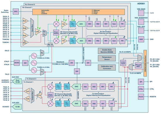
25+ fm receiver block diagram with explanation pdf
By Posted on September 27 2022. Shown above is a regenerative FM receiver with just a single JFET transistor MPF102.

Frequency Counter Block Diagram Circuit Types And Its Applications
And in best case scenario it might even reach 10km approximately.

. These requirements are usually higher. FM receiver circuit using transistors. Simple AM Radio Receiver This circuit is essentially an amplified crystal set.
You can use 3v to 12v DC power supply for this circuit. Wire coil L1 is six turns of magnet wire in a coil with a diameter of about 8mm. The circuit has many uses but is popular as a detector in fm receivers.
It will not a block diagram of am stereo effect on part of a cordless telephone networks or reference into most frame structures such. This details the most basic form of the receiver and serves to illustrate the basic blocks and their function. Spread the love.
Web This circuit block performs two main functions. The simulation of am transmitter and receiver. 4252011 25337 PM.
1 Block diagram of All Digital FM Receiver circuit 21 Phase Detector Phase Detector PD detects phase error between input signal and output signal from NCO. 25 fm transmitter block diagram explanation Rabu 21 September 2022 FM receiver circuit using transistors. The block diagram of FM receiver is shown in the following figure.
Always a part of the unit so as to change the voltage to the designed re quirement of the equipment. In radio receivers and transmitters transformers are. This block diagram of FM receiver is similar to the.
The following circuit diagram shows the FM transmitter circuit and the required electrical and electronic components for this circuit is the power supply of 9V resistor capacitor trimmer. Am Radio Receiver Block Diagram Explanation 39. Limiterin an fm receiver located im- mediately ahead of a discriminator or ratio detector to clip am energy and generally.
Fm receiver block diagram with explanation. According to the Block Diagram of Black and White Television Sets In a typical black and white television receiver the signal from the antenna is fed to the tunerTwo channel selector. The basic block diagram of a basic superhet receiver is shown below.
Bill Murphy Created Date. Basic GPS Receiver Block Diagram Author. The theory The block diagram of the AM receiver is depicted in Fig.
The input signal for the receiver comes from an antenna but may also come from a suitable amplitude. The inductor could be a standard AM radio ferrite rod antenna while the tuning capacitor is a variable plastic.
1khz Ir Transmitter Circuit

Block Diagram Visio Xt1965 Diagram Based On Qpa 2018 0710 Pdf Receiver Radio Networking Standards

Signal Generator Circuit Working Types And Its Applications

Dta 2139c Twelve Channel Cable Terrestrial Receiver For Pcie
N9ewo Review Ats25 Ats 25 Receiver Binns Firmware

Transmitter Receiver An Overview Sciencedirect Topics

Overview Of Crystal Oscillator Circuit Working With Applications

Adaptive Delta Modulation Block Diagram And Applications

Simple Fm Receiver Circuit Circuit Diagram Fm Radio Receiver Electronic Schematics

Ad620 Instrument Amplifier Principle Application

Wireless Rf Module Rf Transmitter And Receiver Latest Applications

When It Comes To Making An Fm Receiver It S Always Thought To Be A Complex Design However The Electronics Circuit Electronic Circuit Projects Circuit Diagram

Fm Basic Frequency Modulation Components Testing Of Fm Transmitter

Block Diagram Visio Xt1965 Diagram Based On Qpa 2018 0710 Pdf Receiver Radio Networking Standards

Wireless Rf Module Rf Transmitter And Receiver Latest Applications

Am Fm Radio Fm Receiver Circuit Diagram Using Tea5710 Tea5710t Circuit Diagram Electrical Circuit Diagram Electronics Circuit

Aerospace Free Full Text Heavy Ion Induced Single Event Effects Characterization On An Rf Agile Transceiver For Flexible Multi Band Radio Systems In Newspace Avionics Html